カテゴリー
2022年 CCNP Enterprise Cisco DDNS VPN コマンド コンピューター トラブルシューティング ルーティング 技術一般 認定資格

Cisco ルーターでリモートアクセス VPN の設定

この設定で、リモートアクセスVPNが正常に張れることまでは確認できたのですが、なぜかルーターのLAN側にルーティングされなくて悩んでます。解決したら、また更新しようと思います。

aaa new-model
!
!
aaa authentication login userauth local
aaa authorization network groupauth local
!
username kkint password 7 kkint-pass
!
crypto isakmp policy 1
 encr 3des
 hash md5
 authentication pre-share
 group 2
!
crypto isakmp client configuration group VPNCLIENT
 key cisco
 dns 172.16.23.254
 domain kkinternational.com
 pool ezvpn1
 save-password
!
crypto isakmp profile vpnclient-profile
   match identity group VPNCLIENT
   client authentication list userauth
   isakmp authorization list groupauth
   client configuration address respond
!
crypto ipsec transform-set myset esp-3des esp-md5-hmac
!
crypto dynamic-map dynmap 1
 set transform-set myset
 set isakmp-profile vpnclient-profile
 reverse-route
!
interface FastEthernet0
 description To the Internet
 ip address dhcp
 duplex auto
 speed auto
 crypto map ezvpnmap
カテゴリー
2022年 CCNP Enterprise Cisco コンピューター ルーティング 冗長化 技術一般 認定資格

FHRP を学ぶ (0) FHRP の種類

PVアクセスランキング にほんブログ村 にほんブログ村 ブログブログへ
にほんブログ村

FHRP: First Hop Redundancy Protocol 

複数のゲートウェイルータを1つのグループに構成し、ゲートウェイルータの高速フェイルオーバを実現させます。簡単に言えば、デフォルトゲートウェイの冗長化です。

通常、PC には1つのデフォルトゲートウェイを設定します。

.254 を Default GW として指定している場合

ゲートウェイが2つ存在したとしても、障害などでデフォルトゲートウェイに指定したルーターにたどり着けなければ、別のセグメントとは通信ができません。

.254 のルーターが障害になると Default GW がなくなる

FHRP の仕組みの基本的なコンセプトは、PC やサーバにとって複数のルータを、仮想的に1つであるかのように見せることにあります。

複数台のルーターを仮想的に1つに見せる

FHRP の種類

HSRP: Hot Standby Routing Protocol 

規格シスコ独自
ルーターの呼び方アクティブルーター、スダンバイルーター

優先度の高いルーターがアクティブとなり通信を処理する。優先度のデフォルト値は 100

VRRP: Virtual Router Redundancy Protocol

規格RFC 3768 で標準化
ルーターの呼び方マスタールーター、バックアップルーター

優先度の高いルーターがアクティブとなり通信を処理する。優先度のデフォルト値は 100

GLBP: Gateway Load Balancing Protocol

規格シスコ独自
ルーターの呼び方AVG (Active Virtual Gateway)
AVF (Active Virtual Forwarder)

ロードバランス方式でパケットを転送

FHRP の動作

複数のルーターやスィッチをグループ化し、デフォルトゲートウェイとなるルーターの高速なフェールオーバーを実現させるプロトコルです。

複数のルーターをグループ化して仮想ルーターを構成し、その仮想ルーターに仮想 IPアドレスを割り当て、それをクライアント PC でデフォルトゲートウェイととして使用します。

複数台のルーターをグループ化

仮想ルーターには、仮想 MAC アドレスも割り当てられます。

パケットを転送しているルーターで障害が起こった場合、グループ内の他のルーターが代理で動き出します。仮想 IPアドレスと仮想 MACアドレスはグループ内で維持されるので、クライアントPCのデフォルトゲートウェイは変わらないという仕組みとなります。

正常時の経路
障害時の経路

次回から、FHRP の1つである HSRP (Hot Standby Routing Protocol) についてまとめていきたいと思います。

この参考書を使って勉強してます。

おもしろかったら、フォローしてください!

世の中には楽しいことがいっぱい - にほんブログ村

関連する記事:

最近の記事:


カテゴリー
2022年 CCNP Enterprise Cisco VPN コマンド コンピューター トラブルシューティング ルーティング 技術一般 認定資格

Cisco ルーターで VPN (2) サイト間 GRE over IPSec VPN 接続

PVアクセスランキング にほんブログ村 にほんブログ村 ブログブログへ
にほんブログ村

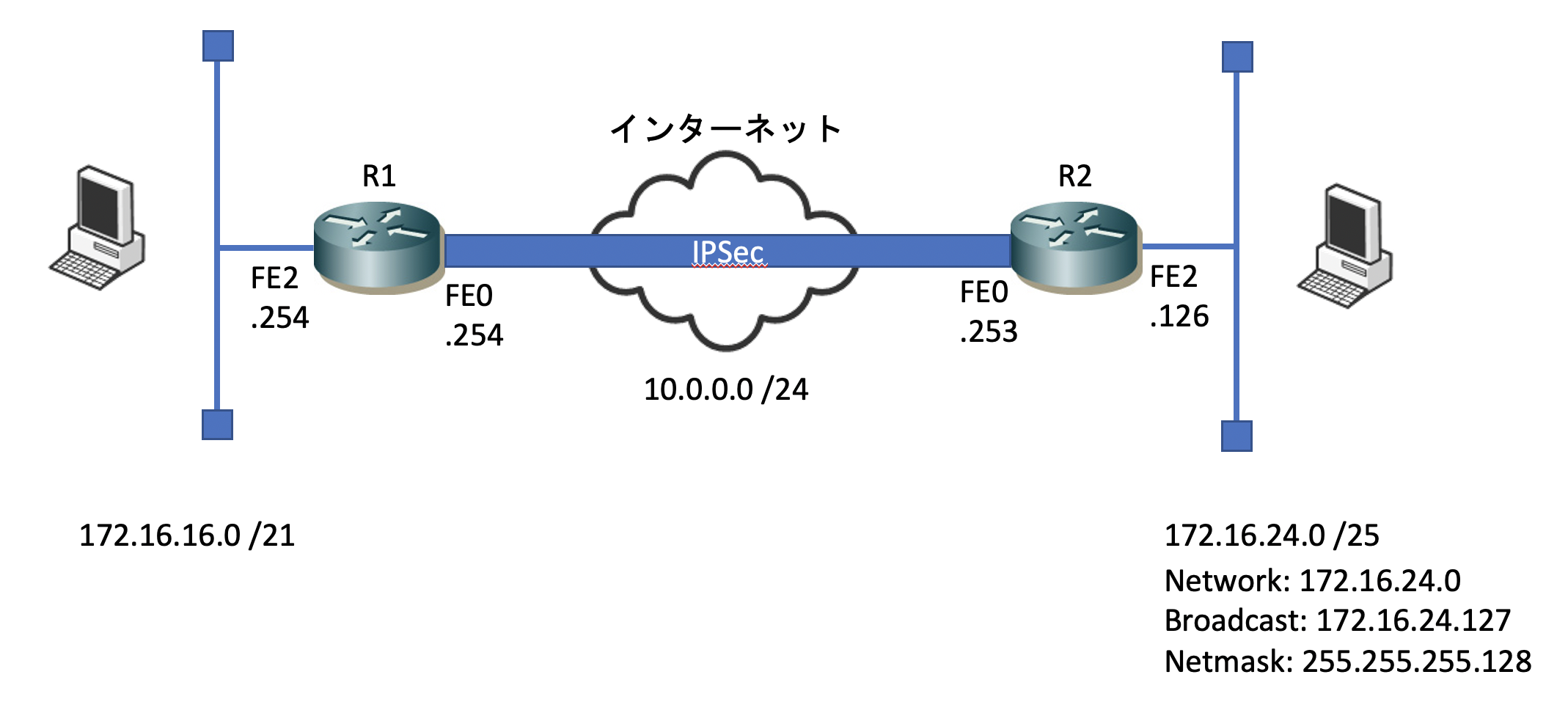
前回は、サイト間 IPSec 接続を試しました。

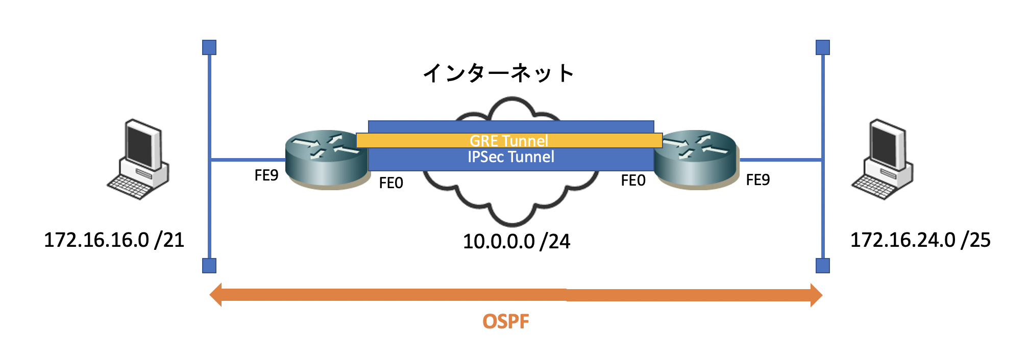
今度は、IPSec トンネルの中に GRE トンネルを通し、インターネット越しにダイナミックルーティングプロトコルのやり取りができるようにしてみたいと思います。

いわゆる GRE over IPSec というやつです。

今回は、両側のルーターで OSPF を動かし、お互いの LAN 側の経路情報をインターネット越しに交換させます。

最終系は、こんなイメージです。

GRE の設定

GRE over IPSec と聞くと、何だか難しく聞こえますが、結局やっていることは、GRE トンネルの設定と IPSec トンネルの設定です。これらを同時に使っているだけです。

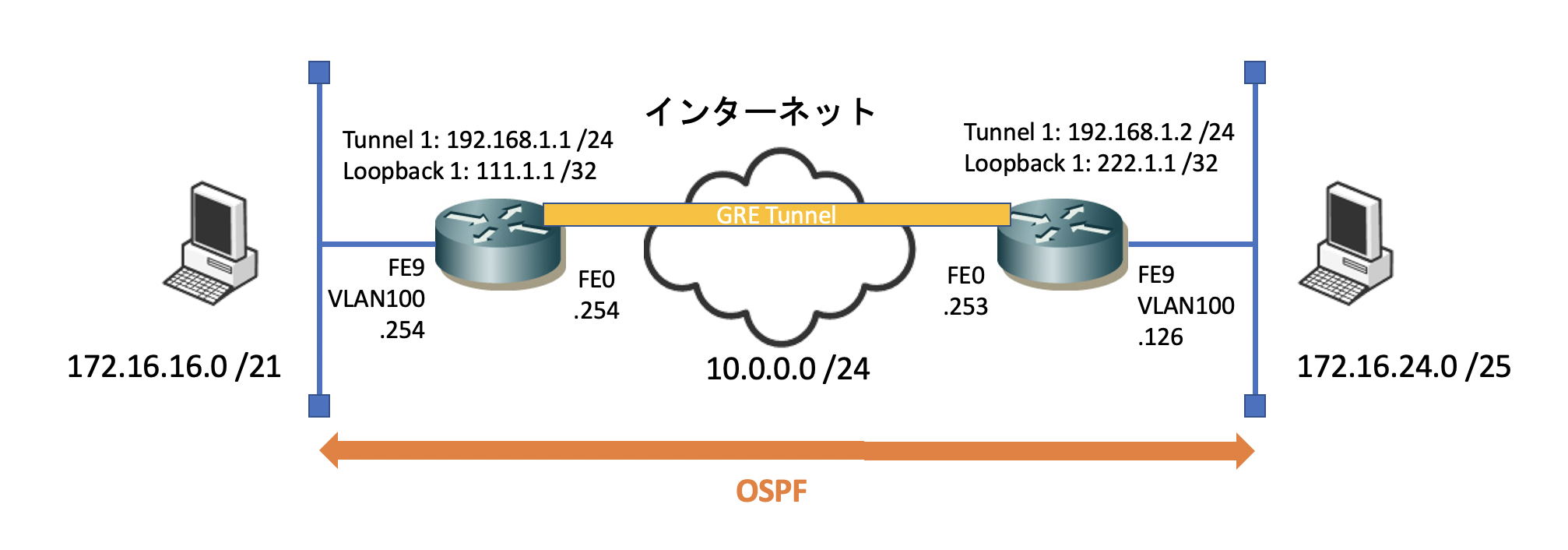
まずは、GRE トンネルの設定から見てみます。

2台のルーター間で GRE トンネルを確立させるためには、Tunnel インターフェスが必要となります。

この Tunnel インターフェースで設定した IPアドレスを使って、通信をカプセリングします。カプセリングをすることにより、ダイナミックルーティングの情報がインターネット越しにできる(GRE トンネルの中を通過する)ようになります。

interface Loopback1
 ip address 111.1.1.1 255.255.255.255
 !
!
interface Tunnel1
 ip address 192.168.1.1 255.255.255.0
 ip mtu 1372
 tunnel source Loopback1 <<< 1
 tunnel destination 222.1.1.1 <<< 2

Tunnel インターフェースでは、IPアドレス以外にも設定すべき項目が 2つあります。この2つの設定も行わないと、インターフェースは Up/Up にはなりません。

  1. Tunnel Source
  2. Tunnel Destination

1 の Tunnel Source ですが、物理インターフェースであっても、Loopback インターフェースであってもどちらでも良いです。

Loopback インターフェースはダウンすることがないですので、こちらを使った方が良いでしょう。特にインターネットルーターで、DHCP でアドレスをもらっている場合、IPアドレスが変わってしまいます。変更の度に Tunnel Source/Destinatio の設定も変えないといけなくなるので、それを避けるためにもLoopback インターフェースが良いです。

Tunnel インターフェースには、他にも色々と設定項目はありますが、上記2つが最低限必要となる設定です。

MTU は 1372 に変更しておきます。

今回の設定では、R1 の Loopback 1 インターフェースのIPアドレスを使用してます。

次に2の Tunnel Destination です。

今回は、対向側になる R2 の Loopback インターフェースの IPアドレスを指定します。

最後に、Network コマンドを使って、Tunnel インターフェースでも OSPF を有効にします。

これにより、Tunnel インターフェースが OSPF の広報をするタイミング GRE トンネルが作成され、OSPF の広報情報が GRE でカプセリングされ、OSPF のネイバーが張れます。

router ospf 1
 log-adjacency-changes
 network 172.16.16.0 0.0.7.255 area 0 <<< LAN segment
 network 192.168.1.1 0.0.0.0 area 0 <<< Tunnel 1

対向側になる R2 の設定は、こんな感じです(GRE の設定に関連する部分のみを抜粋しています)。

interface Loopback1
 ip address 222.1.1.1 255.255.255.255
 !
!
interface Tunnel1
 ip address 192.168.1.2 255.255.255.0
 ip mtu 1372
 tunnel source Loopback1
 tunnel destination 111.1.1.1
 !
router ospf 1
 log-adjacency-changes
 network 172.16.24.0 0.0.0.127 area 0 <<< LAN segment
 network 192.168.1.2 0.0.0.0 area 0 <<< Tunnel 1

これで、GRE トンネル経由で、2つのルーター間の OSPF ネイバーが張れます。

R1#sh ip ospf neighbor 

Neighbor ID     Pri   State           Dead Time   Address         Interface
192.168.1.254     0   FULL/  -        00:00:36    192.168.2.254     Tunnel1

GRE over IPSec の設定

さて、いよいよ本題の GRE over IPSec の設定に入ります。

以下では、暗号化マップを使った IPSec の設定を行います。

と言っても、基本的には先ほどの GRE トンネルの設定と IPSec トンネルの設定を組み合わせるだけです。

組み合わせた時の設定のポイントですが、Crypto マップのポリシーで指定している「IPSec の対象とするアドレス」です。

crypto map M-ipsec 1 ipsec-isakmp 
 set peer 10.0.0.253
 set transform-set IPSEC 
 match address A-ipsec <<< IPSec 対象アドレス

今回、A-ipsec という ACL を指定していますが、その中が以下のものです。

ip access-list extended A-ipsec
 permit gre host 111.1.1.1 host 222.1.1.1

111.1.1.1222.1.1.1 を指定していますね。つまり、Tunnel インターフェースの IPアドレスです。つまり、これらのIPアドレスは、GRE トンネルの Source と Destination で指定ている IPアドレスです。

ということは、動作としては、

  1. OSPF のネイバーを張ろうとすると、
  2. GRE トンネルを張ろうとし、
  3. IPSec トンネルが形成される
  4. それからGRE トンネルが形成され、
  5. OSPF のネイバーが張れる

という流れになります。

同じ考え方で R2 も設定します。

crypto map M-ipsec 1 ipsec-isakmp 
 set peer 10.0.0.254
 set transform-set IPSEC 
 match address A-ipsec
!
ip access-list extended A-ipsec
 permit gre host 222.1.1.1 host 111.1.1.1

これで GRE over IPSec の設定が完了です。R2 のルーティングテーブルを見てみましょう。

R2#sh ip route 
Codes: L - local, C - connected, S - static, R - RIP, M - mobile, B - BGP
       D - EIGRP, EX - EIGRP external, O - OSPF, IA - OSPF inter area 
       N1 - OSPF NSSA external type 1, N2 - OSPF NSSA external type 2
       E1 - OSPF external type 1, E2 - OSPF external type 2
       i - IS-IS, su - IS-IS summary, L1 - IS-IS level-1, L2 - IS-IS level-2
       ia - IS-IS inter area, * - candidate default, U - per-user static route
       o - ODR, P - periodic downloaded static route, H - NHRP, l - LISP
       a - application route
       + - replicated route, % - next hop override, p - overrides from PfR

Gateway of last resort is 0.0.0.0 to network 0.0.0.0

S*    0.0.0.0/0 is directly connected, FastEthernet0
      10.0.0.0/8 is variably subnetted, 3 subnets, 2 masks
O E2     10.0.1.135/32 [110/20] via 192.168.1.1, 00:14:09, Tunnel1
O IA     10.74.6.0/24 [110/1002] via 192.168.1.1, 00:14:09, Tunnel1
O IA     10.200.1.0/24 [110/1002] via 192.168.1.1, 00:14:09, Tunnel1
      172.16.0.0/16 is variably subnetted, 3 subnets, 2 masks
O E2     172.16.0.0/27 [110/20] via 192.168.1.1, 00:14:09, Tunnel1
O E2     172.16.0.32/27 [110/20] via 192.168.1.1, 00:14:09, Tunnel1
O        172.16.16.0/21 [110/1001] via 192.168.1.1, 00:14:09, Tunnel1
      192.168.1.0/24 is variably subnetted, 2 subnets, 2 masks
C        192.168.1.0/24 is directly connected, Tunnel1
L        192.168.1.2/32 is directly connected, Tunnel1
      222.1.1.0/32 is subnetted, 1 subnets
C        222.1.1.1 is directly connected, Loopback1

R1 の LAN 側になるセグメント情報(172.16.16.0 /21)が R2 のルーティングテーブル上で見えますね。これで GRE over IPSec の設定は完了です。

ですがここで一つ疑問が湧いてきました。

Loopback インターフェースで指定している IPアドレスって、到達不能のものであるはずなのに、GRE トンネルってどうやって張れるのだろう?

不思議だったので調べてみたら、Cisco の GRE の説明のページに記載がありました。

有効なトンネル送信元は、それ自体がアップ/アップ状態で、IPアドレスが設定されているインターフェースで構成されます。

有効なトンネル宛先は、ルーティング可能な宛先です。ただし、到達可能である必要はありません。

Tunnel Destination の IPアドレスは、到達可能でなくても良いのです。なるほどです。

設定内容

R1

R1#sh run 
Building configuration...

Current configuration : 2235 bytes
!
! Last configuration change at 01:30:10 UTC Wed Feb 14 2022
!
version 15.0
service timestamps debug datetime msec
service timestamps log datetime msec
no service password-encryption
!
hostname R1
!
boot-start-marker
boot-end-marker
!
enable secret 5 cisco
enable password cisco-ena
!
no aaa new-model
!
!
!
!
!
dot11 syslog
ip source-route
!
!
!
!
ip cef
no ipv6 cef
!
multilink bundle-name authenticated
!
!
!
license udi pid CISCO1812-J/K9 sn xxxxxxx
!
!
! 
!
crypto isakmp policy 10
 hash md5
 authentication pre-share
crypto isakmp key vpnuser address 10.0.0.253
!
!
crypto ipsec transform-set IPSEC esp-3des esp-md5-hmac 
 mode transport
!
crypto map M-ipsec 1 ipsec-isakmp 
 set peer 10.0.0.253
 set transform-set IPSEC 
 match address A-ipsec
!
!
!
!
!
interface Loopback1
 ip address 111.1.1.1 255.255.255.255
 !
!
interface Tunnel1
 ip address 192.168.1.1 255.255.255.0
 ip mtu 1372
 tunnel source Loopback1
 tunnel destination 222.1.1.1
 !
!
interface BRI0
 no ip address
 encapsulation hdlc
 shutdown
 !
!
interface FastEthernet0
 ip address 10.0.0.254 255.255.255.0
 duplex auto
 speed auto
 crypto map M-ipsec
 !
!
interface FastEthernet1
 no ip address
 duplex auto
 speed auto
 !
!
interface FastEthernet2
 switchport access vlan 100
 !
!
interface FastEthernet3
 switchport access vlan 100
 !
!
interface FastEthernet4
 switchport access vlan 100
 !
!
interface FastEthernet5
 switchport access vlan 100
 !
!
interface FastEthernet6
 switchport access vlan 100
 !
!
interface FastEthernet7
 switchport access vlan 100
 !
!
interface FastEthernet8
 switchport access vlan 100
 !
!
interface FastEthernet9
 switchport access vlan 100
 !
!
interface Vlan1
 no ip address
 !
!
interface Vlan100
 ip address 172.16.23.254 255.255.248.0
 !
!
router ospf 1
 log-adjacency-changes
 network 172.16.16.0 0.0.7.255 area 0
 network 192.168.1.1 0.0.0.0 area 0
!
ip forward-protocol nd
no ip http server
no ip http secure-server
!
!
ip route 0.0.0.0 0.0.0.0 FastEthernet0
!
ip access-list extended A-ipsec
 permit gre host 111.1.1.1 host 222.1.1.1
!
!
!
!
!
!
!
control-plane
 !
!
!
line con 0
 password cisco-con
 login
line aux 0
line vty 0 4
 password cisco-vty
 login
!
end

R2

R2#sh run 
Building configuration...

Current configuration : 2393 bytes
!
! Last configuration change at 01:19:06 UTC Wed Feb 14 2022
!
version 15.0
service timestamps debug datetime msec
service timestamps log datetime msec
no service password-encryption
!
hostname R2
!
boot-start-marker
boot-end-marker
!
enable secret 5 cisco
enable password cisco-ena
!
no aaa new-model
!
!
!
memory-size iomem 25
!
!
dot11 syslog
ip source-route
!
!
!
!
ip cef
no ip domain lookup
no ipv6 cef
!
multilink bundle-name authenticated
!
!
!
license udi pid CISCO1812-J/K9 sn xxxxxx
!
!
vlan 100
 name home-data
!
vlan 111
 name MGMT
!
vlan 200
 name PBR-test
!
! 
!
crypto isakmp policy 10
 hash md5
 authentication pre-share
crypto isakmp key vpnuser address 10.0.0.254
!
!
crypto ipsec transform-set IPSEC esp-3des esp-md5-hmac 
 mode transport
!
crypto map M-ipsec 1 ipsec-isakmp 
 set peer 10.0.0.254
 set transform-set IPSEC 
 match address A-ipsec
!
!
!
!
!
interface Loopback1
 ip address 222.1.1.1 255.255.255.255
 !
!
interface Tunnel1
 ip address 192.168.1.2 255.255.255.0
 ip mtu 1372
 tunnel source Loopback1
 tunnel destination 111.1.1.1
 !
!
interface BRI0
 no ip address
 encapsulation hdlc
 shutdown
 !
!
interface FastEthernet0
 ip address 10.0.0.253 255.255.255.0
 duplex auto
 speed auto
 crypto map M-ipsec
 !
!
interface FastEthernet1
 no ip address
 duplex auto
 speed auto
 !
!
interface FastEthernet2
 switchport access vlan 100
 !
!
interface FastEthernet3
 switchport access vlan 100
 !
!
interface FastEthernet4
 switchport access vlan 100
 !
!
interface FastEthernet5
 switchport access vlan 100
 !
!
interface FastEthernet6
 switchport access vlan 100
 !
!
interface FastEthernet7
 switchport access vlan 100
 !
!
interface FastEthernet8
 switchport access vlan 100
 !
!
interface FastEthernet9
 switchport access vlan 100
 !
!
interface Vlan1
 no ip address
 !
!
interface Vlan100
 ip address 172.16.24.126 255.255.255.128
 !
!
router ospf 1
 log-adjacency-changes
 network 172.16.24.0 0.0.0.127 area 0
 network 192.168.1.2 0.0.0.0 area 0
!
ip forward-protocol nd
no ip http server
no ip http secure-server
!
!
ip route 0.0.0.0 0.0.0.0 FastEthernet0
!
ip access-list extended A-ipsec
 permit gre host 222.1.1.1 host 111.1.1.1
!
!
!
!
!
!
!
control-plane
 !
!
!
line con 0
 password cisco-con
 login
line aux 0
line vty 0 4
 password cisco-vty
 login
!
end

おもしろかったら、フォローしてください!

世の中には楽しいことがいっぱい - にほんブログ村

関連する記事

最近の記事:

カテゴリー
2022年 CCNP Enterprise Cisco VPN コマンド コンピューター トラブルシューティング ルーティング 技術一般 認定資格

Cisco ルーターで VPN (1) サイト間 IPSec VPN 接続

PVアクセスランキング にほんブログ村 にほんブログ村 ブログブログへ
にほんブログ村

私の自宅では、インターネットルーターに Cisco ルーターを使用していますので、父親の家でも Cisco ルーターを使って、父親の家と私の自宅を IPSec VPN で接続してみようかなと考えました。

以前は、Buffalo ルーターを使って、父親の家と VPN 接続していたのですが、それが壊れてしまいました。これがきっかけです。

今回考えているのは、以下のような構成です。

単純にインターネット越しに 2つのサイトを VPN 接続するという構成です。

今回の動作確認で使用したのは、Cisco 1812J です。2台のルーターをバックトゥバックで接続しています。

サイト間 VPN の動作確認

自宅に 2台の Cisco ルーターを用意し、テスト構成を作成して、IPSec の設定を行いました。

テスト構成は、以下のアドレス体系としています。

以下のIPSecの設定は、暗号化マップを使った方式となります。

IPsec の設定

  1. まず、ISAKMP ポリシーを作成します。
  2. ここでは、「共通鍵を使用しますよ」と宣言を行います。
  3. 次に、IPSec 接続の際に使用するキーを指定し、そして、そのキーを使用して IPSec 接続する対向先のルーターの IPアドレスを指定します。
crypto isakmp policy 10 <<< 1
 hash md5
 authentication pre-share <<< 2
 crypto isakmp key vpnuser address 10.0.0.253 <<< 3

10.0.0.253 が R2 の Fast Ethernet の IPアドレスです。これは、インターネット越しで到達可能な IPアドレスである必要があります。

つまり、「このインターフェースとの IPSec 接続には、このキーを使用しましょう」ということです。

次に、Transform セットを作成します。

ここでは、IPSec 接続の際に使用する暗号化の方式を定義します。

crypto ipsec transform-set myset esp-des esp-md5-hmac 

ここで使用している「myset」が、このTransform セットの名前になります。

使用する暗号化方式は、「esp-des esp-md5-hmac 」です。

次に、Cryptoマップ(暗号化マップ)を作成します。

このマップ内では、

  1. どの IPアドレスが IPSec の接続先なのか
  2. どの通信を IPSec トンネルの対象にするのか(トンネルの中に通すのか)
  3. 使用する Transform セットの名前

を定義します。

crypto map mymap 10 ipsec-isakmp 
 set peer 10.0.0.253 <<< 1
 set transform-set myset <<< 2
 match address 100 <<< 3
  • この Crypto マップの名前は「mymap」としています。
  • set peer で指定しているのが、IPSec の張り先となるIPアドレスです。
  • このマップを使用する時には、「myset」という Transform セットを使いなさいとします。
  • match address でしてしている番号が、ACL の番号となります。この ACL で IPSec トンネルの中に入れる対象となるトラフィックはどれなのかを定義します。

最後に、ACL を作成します。

2台のルーターの、それぞれの LAN 側のセグメントを指定します。

access-list 100 permit ip 172.16.16.0 0.0.7.255 172.16.24.0 0.0.0.127

「R1 の LAN 側(172.16.16.0 /21) から、R2 の LAN 側(172.16.24.0 /25) へ向かうトラフィックを IPSec トンネルの中に入れますよ」ということです。

これで、IPSec の基本設定は完了です。

IPSec のCrypto マップを適用

仕上げとして、作成した Crypto マップを、対象となるインターフェースに適用しましょう。

適用するインターフェースは、WAN 側(インターネット側)に面しているインターフェースです。つまり、対向側ルーターが IPSec トンネルを張ってくる宛先となるインターフェースです。

先ほど作成した Crypto マップは「mymap」でしたね。

crypto map コマンドで、そのマップの名前を指定して、インターフェースに適用します。

interface FastEthernet0
 ip address 10.0.0.254 255.255.255.0
 duplex auto
 speed auto
 crypto map mymap

私が Crypto マップを適用しているのは、Fast Ethernet 0 インターフェースになります。

そうそう、このルーターはインターネットルーターですので、デフォルトルートは Fast Ethernet 0 (インターネットに面しているインターフェース)に向けておきましょう。

これを忘れると、インターネット向けの通信ができません。

ip route 0.0.0.0 0.0.0.0 FastEthernet0

これで、IPSec の設定適用は完了です。

これと同じことを、R2 側でも行います。IPSec トンネルの接続先が R1 になる点だけが異なります。

以下、IPSec 接続に必要な部分の設定のみを抜粋しています。

crypto isakmp policy 10
 hash md5
 authentication pre-share
crypto isakmp key vpnuser address 10.0.0.254
!
!
crypto ipsec transform-set myset esp-des esp-md5-hmac 
!
crypto map mymap 10 ipsec-isakmp 
 set peer 10.0.0.254
 set transform-set myset 
 match address 100
!
!
interface BRI0
 no ip address
 encapsulation hdlc
 shutdown
 !
!
interface FastEthernet0
 ip address 10.0.0.253 255.255.255.0
 duplex auto
 speed auto
 crypto map mymap
 !
!
ip route 0.0.0.0 0.0.0.0 FastEthernet0
!
access-list 100 permit ip 172.16.24.0 0.0.0.127 172.16.16.0 0.0.7.255

IPSec の接続確認コマンド

実際に通信をして確認をしてみます。

  • show crypto isakmp sa
R1#sh crypto isakmp sa 
IPv4 Crypto ISAKMP SA
dst             src             state          conn-id status
10.0.0.253       10.0.0.254       QM_IDLE           2001 ACTIVE

ステータスが「QM_IDLE」になっていれば、ISAKMP 接続は完了です。

「QM_IDLE」以外のステータスの場合、このページが参考になります。

  • show crypto ipsec sa
C1812-test#sh crypto ipsec sa 

interface: FastEthernet0
    Crypto map tag: M-ipsec, local addr 10.0.0.254

   protected vrf: (none)
   local  ident (addr/mask/prot/port): (0.0.0.0/255.255.255.255/47/0)
   remote ident (addr/mask/prot/port): (0.0.0.0/255.255.255.255/47/0)
   current_peer 10.0.0.253 port 500
     PERMIT, flags={origin_is_acl,}
    #pkts encaps: 97, #pkts encrypt: 97, #pkts digest: 97
    #pkts decaps: 94, #pkts decrypt: 94, #pkts verify: 94
    #pkts compressed: 0, #pkts decompressed: 0
    #pkts not compressed: 0, #pkts compr. failed: 0
    #pkts not decompressed: 0, #pkts decompress failed: 0
    #send errors 134, #recv errors 0

     local crypto endpt.: 10.0.0.254, remote crypto endpt.: 10.0.0.253
     path mtu 1500, ip mtu 1500, ip mtu idb FastEthernet0
     current outbound spi: 0xD8FB69D5(3640355285)
     PFS (Y/N): N, DH group: none

     inbound esp sas:
      spi: 0xD6CE8456(3603858518)
        transform: esp-3des esp-md5-hmac ,
        in use settings ={Tunnel, }
        conn id: 1, flow_id: Onboard VPN:1, sibling_flags 80000046, crypto map: M-ipsec
        sa timing: remaining key lifetime (k/sec): (4420763/2793)
        IV size: 8 bytes
        replay detection support: Y
        Status: ACTIVE

     inbound ah sas:

     inbound pcp sas:

     outbound esp sas:
      spi: 0xD8FB69D5(3640355285)
        transform: esp-3des esp-md5-hmac ,
        in use settings ={Tunnel, }
        conn id: 2, flow_id: Onboard VPN:2, sibling_flags 80000046, crypto map: M-ipsec
        sa timing: remaining key lifetime (k/sec): (4420762/2793)
        IV size: 8 bytes
        replay detection support: Y
        Status: ACTIVE

     outbound ah sas:

     outbound pcp sas:

カウンターの数値が上がっていれば、IPSec トンネルの中に通信が通過しています。

うまく接続できない時は、デバッグコマンドが役に立ちます。

  • debug crypto isakmp 
  • debug crypto ipsec

設定内容

R1

R1#sh run 
Building configuration...

Current configuration : 1842 bytes
!
! Last configuration change at 06:21:16 UTC Tue Feb 23 2021
!
version 15.0
service timestamps debug datetime msec
service timestamps log datetime msec
no service password-encryption
!
hostname R1
!
boot-start-marker
boot-end-marker
!
!
no aaa new-model
!
!
!
!
!
dot11 syslog
ip source-route
!
!
!
!
ip cef
no ipv6 cef
!
multilink bundle-name authenticated
!
!
!
license udi pid CISCO1812-J/K9 sn xxxxxxx
!
!
! 
!
crypto isakmp policy 10
 hash md5
 authentication pre-share
crypto isakmp key vpnuser address 10.0.0.253
!
!
crypto ipsec transform-set myset esp-des esp-md5-hmac 
!
crypto map mymap 10 ipsec-isakmp 
 set peer 10.0.0.253
 set transform-set myset 
 match address 100
!
!
!
!
!
interface BRI0
 no ip address
 encapsulation hdlc
 shutdown
 !
!
interface FastEthernet0
 ip address 10.0.0.254 255.255.255.0
 duplex auto
 speed auto
 crypto map mymap
 !
!
interface FastEthernet1
 no ip address
 duplex auto
 speed auto
 !
!
interface FastEthernet2
 switchport access vlan 100
 !
!
interface FastEthernet3
 switchport access vlan 100
 !
!
interface FastEthernet4
 switchport access vlan 100
 !
!
interface FastEthernet5
 switchport access vlan 100
 !
!
interface FastEthernet6
 switchport access vlan 100
 !
!
interface FastEthernet7
 switchport access vlan 100
 !
!
interface FastEthernet8
 switchport access vlan 100
 !
!
interface FastEthernet9
 switchport access vlan 100
 !
!
interface Vlan1
 no ip address
 !
!
interface Vlan100
 ip address 172.16.23.254 255.255.248.0
 !
!
router ospf 1
 log-adjacency-changes
 network 172.16.16.0 0.0.7.255 area 0
!
ip forward-protocol nd
no ip http server
no ip http secure-server
!
!
ip route 0.0.0.0 0.0.0.0 FastEthernet0
!
access-list 100 permit ip 172.16.16.0 0.0.7.255 172.16.24.0 0.0.0.127
!
!
!
!
!
!
control-plane
 !
!
!
line con 0
line aux 0
line vty 0 4
 login
!
end

R2

R2#sh run 
Building configuration...

Current configuration : 1980 bytes
!
! Last configuration change at 06:07:15 UTC Sun Feb 13 2022
!
version 15.0
service timestamps debug datetime msec
service timestamps log datetime msec
no service password-encryption
!
hostname R2
!
boot-start-marker
boot-end-marker
!
!
no aaa new-model
!
!
!
memory-size iomem 25
!
!
dot11 syslog
ip source-route
!
!
!
!
ip cef
no ipv6 cef
!
multilink bundle-name authenticated
!
!
!
license udi pid CISCO1812-J/K9 sn xxxxxxx
!
!
vlan 100
 name home-data
!
vlan 111
 name MGMT
!
vlan 200
 name PBR-test
!
! 
!
crypto isakmp policy 10
 hash md5
 authentication pre-share
crypto isakmp key vpnuser address 10.0.0.254
!
!
crypto ipsec transform-set myset esp-des esp-md5-hmac 
!
crypto map mymap 10 ipsec-isakmp 
 set peer 10.0.0.254
 set transform-set myset 
 match address 100
!
!
!
!
!
interface BRI0
 no ip address
 encapsulation hdlc
 shutdown
 !
!
interface FastEthernet0
 ip address 10.0.0.253 255.255.255.0
 duplex auto
 speed auto
 crypto map mymap
 !
!
interface FastEthernet1
 no ip address
 duplex auto
 speed auto
 !
!
interface FastEthernet2
 switchport access vlan 100
 !
!
interface FastEthernet3
 switchport access vlan 100
 !
!
interface FastEthernet4
 switchport access vlan 100
 !
!
interface FastEthernet5
 switchport access vlan 100
 !
!
interface FastEthernet6
 switchport access vlan 100
 !
!
interface FastEthernet7
 switchport access vlan 100
 !
!
interface FastEthernet8
 switchport access vlan 100
 !
!
interface FastEthernet9
 switchport access vlan 100
 !
!
interface Vlan1
 no ip address
 !
!
interface Vlan100
 ip address 172.16.24.126 255.255.255.128
 !
!
router ospf 1
 log-adjacency-changes
 network 172.16.24.0 0.0.0.127 area 0
!
ip forward-protocol nd
no ip http server
no ip http secure-server
!
!
ip route 0.0.0.0 0.0.0.0 FastEthernet0
!
access-list 100 permit ip 172.16.24.0 0.0.0.127 172.16.16.0 0.0.7.255
!
!
!
!
!
!
control-plane
 !
!
!
line con 0
line aux 0
line vty 0 4
 login
!
end

おもしろかったら、フォローしてください!

世の中には楽しいことがいっぱい - にほんブログ村

関連する記事

最近の記事:

カテゴリー
2022年 CCNP Enterprise Cisco DDNS コマンド コンピューター ルーティング 技術一般 認定資格

Cisco ルーターでダイナミック DNS を使う

PVアクセスランキング にほんブログ村 にほんブログ村 ブログブログへ
にほんブログ村

自宅のインターネットルーターで Cisco 891F を使用していて、ダイナミック DNS が使いたかったので、設定をまとめてみました。

ちなみに、私が契約しているダイナミック DNS は、Dyndns です。

インターネット上の DNS サーバーを参照できるようにします。

  • ip dns server: DNS サーバー参照を有効化
  • ip name-server: 参照する DNS サーバーの IPアドレス
C892-02# configure terminal
C892-02(config)# ip dns server
C892-02(config)# ip name-server 4.2.2.6

DDNS の設定を入れていきます。

  • ip ddns update method: 契約している DDNS のサービス
  • http: HTTP を使用して更新

この例では、Dyndnsをサービスとして使っています。

C892-02(config)#ip ddns update method DynDNS
C892-02(DDNS-update-method)#http

次に、Dyndns で契約しているサービスのアカウント情報を指定します。Dyndns の場合、構文は以下の内容になります。

https://username:password@members.dyndns.org/nic/update?system=dyndns&hostname=&myip=

C892-02(DDNS-HTTP)# add http://kkinternational:pass-kk@members.dyndns.org/nic/update?system=dyndns&hostname=<h>&myip=<a>

次に、アップデートのインターバルを指定します。

  • interval maximum: DDNS の更新間隔

日 時間 分 秒 の順になります。以下の例だと 5分毎という指定です。このインターバルは時間が短すぎると、サービスによっては拒否されますので、適当な長さで指定した方が良いです。

C892-02(DDNS-HTTP)# interval maximum 0 0 5 0

これで、ダイナミック DNS の設定は完了です。

DDNS として No-IP を使用している場合、こちらが参考になります。

最後に、この設定をインターネットに面しているインターフェースに適用していきます。

  • ip ddns update hostname: 契約している DDNS のホスト名
  • ip ddns update: 契約しているサービス名
C892-02(DDNS-update-method)# interface dialer0
C892-02(config-if)# ip ddns update hostname kkinternational.dyndns.org
C892-02(config-if)# ip ddns update dyndns
C892-02(config-if)# ip address dhcp

動作確認には、このデバッグコマンドが使えます。

C892-02#debug ip ddns update 
Dynamic DNS debugging is on

この設定を使って、リモートからの IPSec VPN 接続を行おうと設定をしています。こちらの設定についても、まとめたら公開していきたいと思います。

おもしろかったら、フォローしてください!

世の中には楽しいことがいっぱい - にほんブログ村

関連する記事:

最近の記事: